You can configure the nodes easily using LSF Manager, using the configuration tool. An overview of the configuration steps is:
- Configure socket endpoints used to send and receive local IP traffic.
- Configure WebRTC peer connections and data channels endpoints that will automatically establish remote connections between LSF Gateway nodes.
- Set up internal flows, which look like internal wiring, between the socket and data channel endpoint
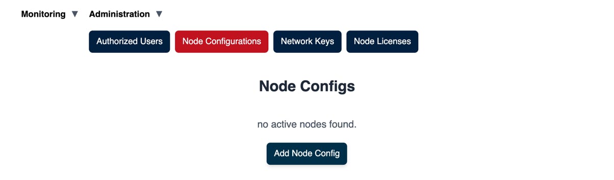
Step 1: Open the Node Configuration Panel
- Log in to LSF Manager.
- Navigate to Administration → Node Configuration.
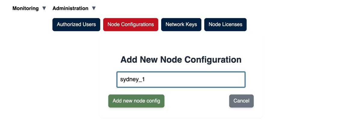
- Click Add Node Config.
- In the dialog, enter your node_id (must match your gateway’s ID) and hit Add.
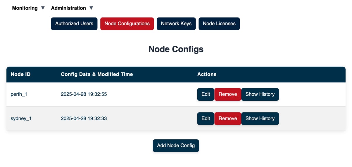
- Click the new entry to open its settings.
Tip: LSFGateway nodes automatically pull the config whose ID matches their node_id.
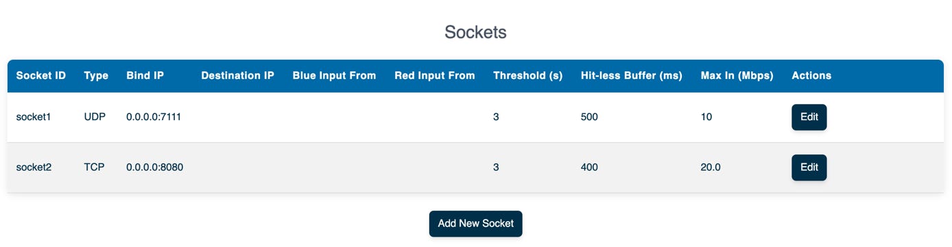
Step 2: Add Socket Endpoints
- Scroll down to Sockets and click + Add New Socket.
- Fill in the fields:
- Socket ID: a unique label (e.g. udp_input)
- TCP/UDP: toggle on if you need TCP (default is UDP)
- Bind IP: local IP:port (UDP unicast/multicast or TCP listener)
- Destination IP: remote IP:port
- Blue input From: input source from one of the other socket or data channel endpoints
- Red input From: input source from one of the other socket or data channel endpoints
- Threshold: If the blue and red inputs did not originate from the same socket on a remote node, they are not in sync, and can not be merged using hitless protection. When they are not in sync, the gateway nodes can still switch between them but they do that if the active input doesn’t receive any data within the given threshold value.
- Hitless buffer: Buffer size for seamless protection switching.
- Max In: Rate limiter of input traffic. Will drop packets if the rate exceeds given limit.
- Protection Switching Modes:
- A) Single Input: only blue or red
- B) Bonding: outputs the packet that arrives first, if blue and red are generated from the same source
- C) Redundant: If bonding was not possible, switches between red and blue when one stalls past the threshold
- Click Save and repeat for each interface.
Step 3: Configure Connectivity
You have two connectivity options: WebRTC and SRT links. WebRTC offers greater flexibility, enabling the seamless transmission of any TCP or UDP data. In contrast, SRT is particularly suited for long-distance video transport. WebRTC’s ability to bypass firewalls and establish connections autonomously without the need for manual firewall port opening is a significant advantage. Conversely, SRT typically requires careful planning of IP addresses and the explicit opening of firewall ports.
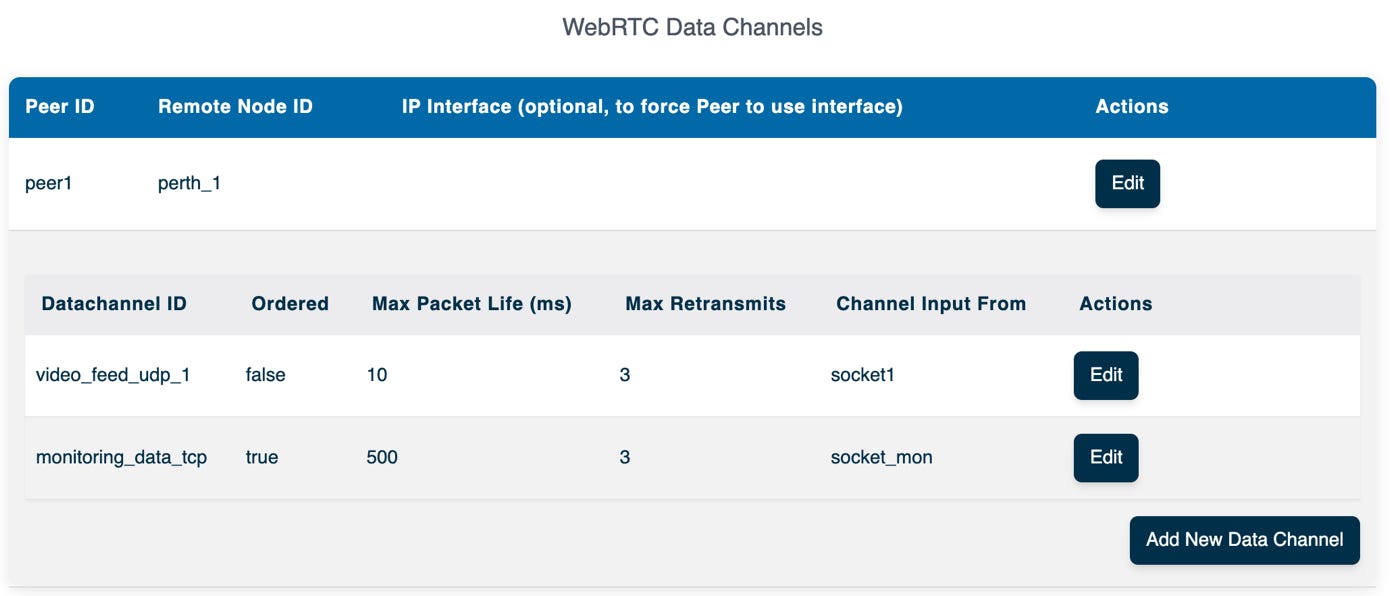
Option 3a: Configure WebRTC Data Channels
There are two stages involved in building WebRTC channels. The first stage is establishing a WebRTC Peer Connection, which creates a secure, encrypted channel between two nodes.
- Navigate to WebRTC Endpoints and click + Add New Peer.
- Fill in the fields:
- Peer ID: A unique identifier that must be the same on both ends of the peer connection.
- Remote Node ID: The Node ID of the remote node. This is the node_id value you used when you started a ne lsfgateway node in the previouse steps.
- IP Interface: Optionally, provide an IP address (or IP:Port such as 10.0.0.1:5001) to tunnel all WebRTC STUN server traffic through the specific IP and port number.
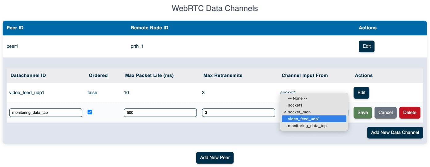
- Once the Peer Connection is configured, you can add Data Channels within the WebRTC connection. Typically, you configure one data channel for each IP flow. Fill in the following:
- Datachannel ID: A Unique name per channel
- Ordered: ‘true’ to guarantee in-order delivery (note that this may add retransmission delays)
- Max Packet Life: (unordered only) Maximum time to wait before dropping a late packet
- Max Retransmits: Maximum number of retransmission attempts before dropping a message
- Channel Input From: The ID of the socket or channel whose data you want to send over this data channel
Option 3b: Configure SRT Channels
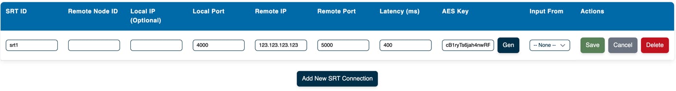
- Navigate to SRT Connections and click + Add New SRT Connection.
- Fill in the fields:
- SRT ID: Unique identifier for the SRT endpoint.
- Remote Node ID: Optional, provide if the other end is another LSFGateway node. When the remote node ID is provided, the remote node IP address is no longer required. LSFGateway will locate the other LSFGateway node using the backend control system.
- Local IP: Optional local address to bind the SRT connection (useful when you have multiple NICs).
- Local Port: Port to bind locally (0–65535). You can provide 0 if you wish for the operating system to locate any available local port. However, as an SRT listener, you must specify the port number you intend to bind to.
- Remote IP: The remote IP address is only required if the remote node is a generic SRT device (i.e., it is not another LSFGateway node). Additionally, this is only required if you wish to configure SRT as the Caller.
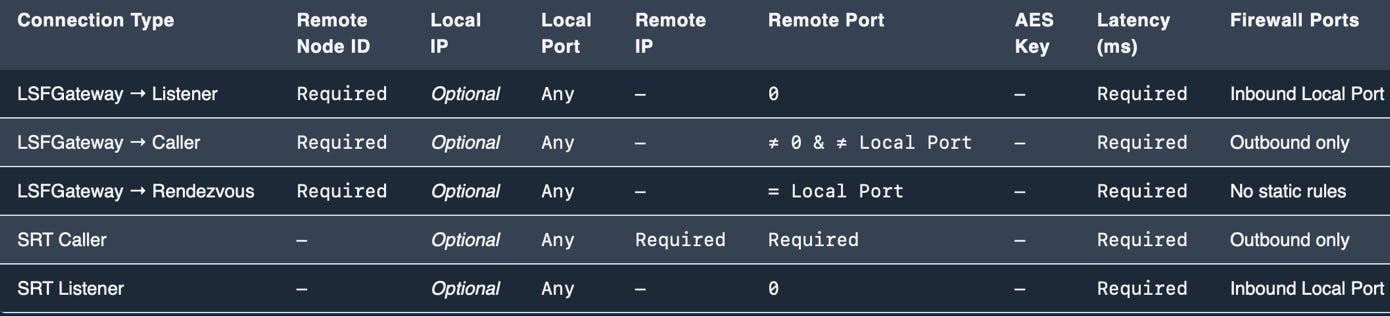
- Remote Port:
- 0 → Listener mode (inbound only).
- ≠ 0 & ≠ Local Port → Caller mode (outbound).
- = Local Port → Rendezvous mode (NAT hole‑punching) only when both ends are LSFGateway nodes.
- AES Key: Encryption key (auto-generating when connecting to another LSFGateway node.).
- Latency (ms): Maximum one‑way latency tolerance. This is the ARQ buffer employed to mitigate network errors. Typically, it is recommended to have a buffer size that exceeds the total end-to-end network delay. In instances where the link quality is poor and packet loss occurs, increasing the latency of the buffer can be beneficial.
- Input Source: Socket or data‑channel providing input.
Reference table for different connection modes:
Below follows an example showing hoot configure a SRT caller:
Step 4: Define Internal Flows & Protection
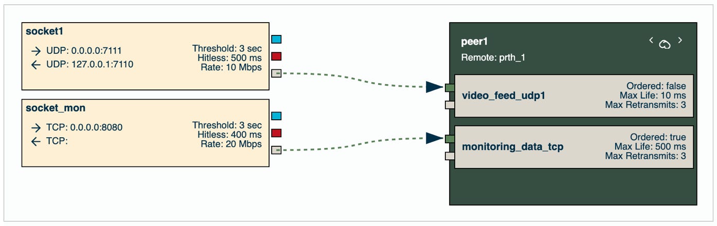
The configuration supports defining multiple sockets and WebRTC data channels, enabling endpoints for both inputs and outputs.
The final step is to wire the internal flows by connecting the endpoints together. This is easily done by selecting which socket or data channel endpoint should serve as the input for a given endpoint.
An example is shown below:
A visual overview of your configuration is available at the top of the page.
Review the configuration parameters and flow paths to ensure everything is set up as expected.
When you are done, you have the following options:
- Download File: Downloads the configuration file to your device. You can upload it again to another configuration if needed.
- Save: Saves the configuration to the database without forcing a running lsfgateway node to use it immediately. The node will load the saved configuration the next time it reboots.
- Apply: Saves the configuration to the database and sends it to the node (if it is turned on and available). The node will reload the updated configuration and apply the changes immediately.