Manual
Welcome to Live Stream Fleet Solution Manual
Manual
Welcome to Live Stream Fleet Solution Manual
Example: RTP Video Transport Over WebRTC
./lsfgateway --node_id node-a \
--account_id 8ab79469-5ddb-486b-9f7f-146864306b02 \
--secret_key e657f0e70d78c3bcecdb9670d434982c
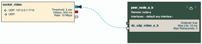
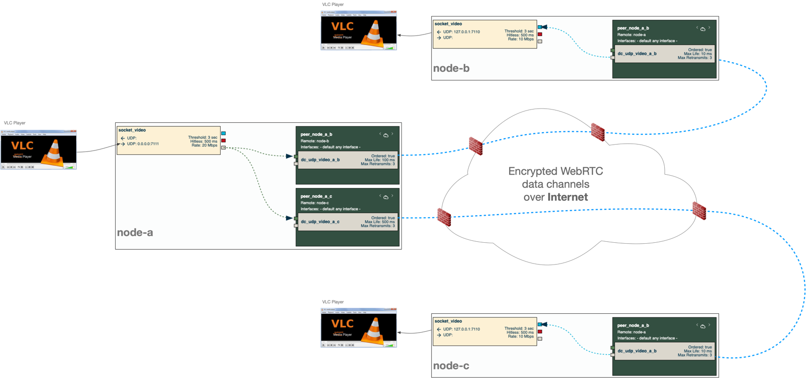
In here, we will configure two LSFGateway nodes to send an RTP video stream from Node A to Node B, over Internet using UDP data channels, as shown in the diagram below.
Prerequisites:
First, please make sure you have installed three lsfgateway nodes and that you have access to the LSF Manager web app, following the instructions in the Config Prerequisites page.
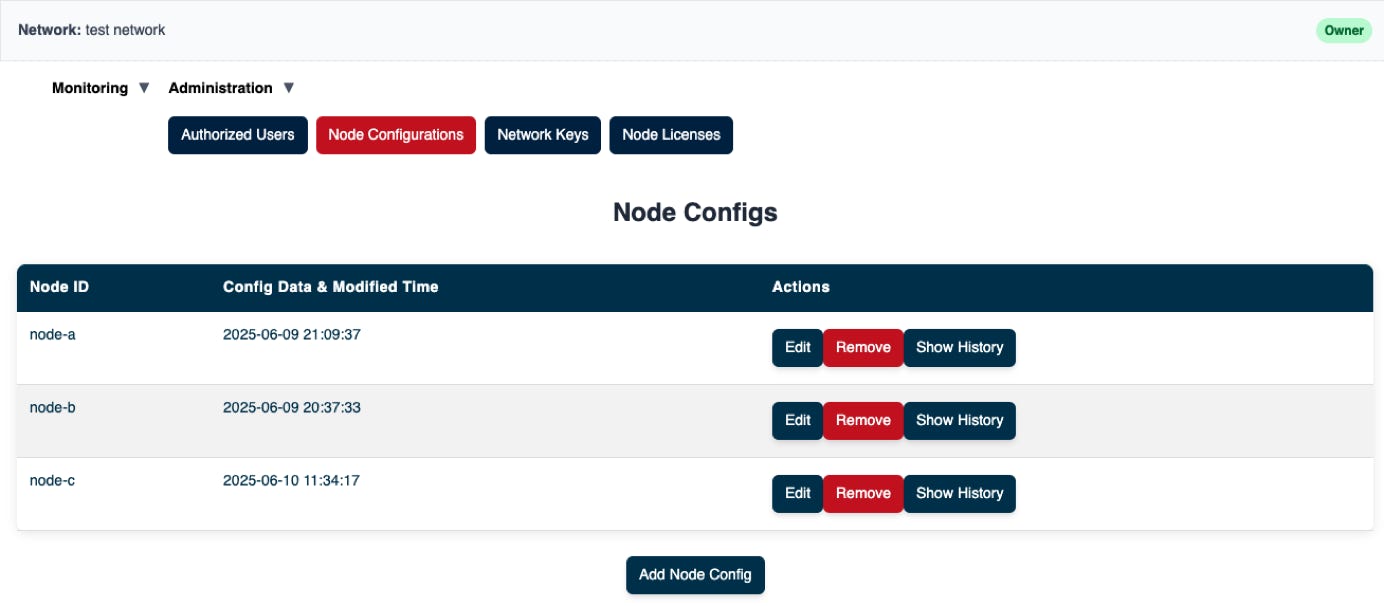
Create the empty node configs
The result looks like something like the screenshot below:
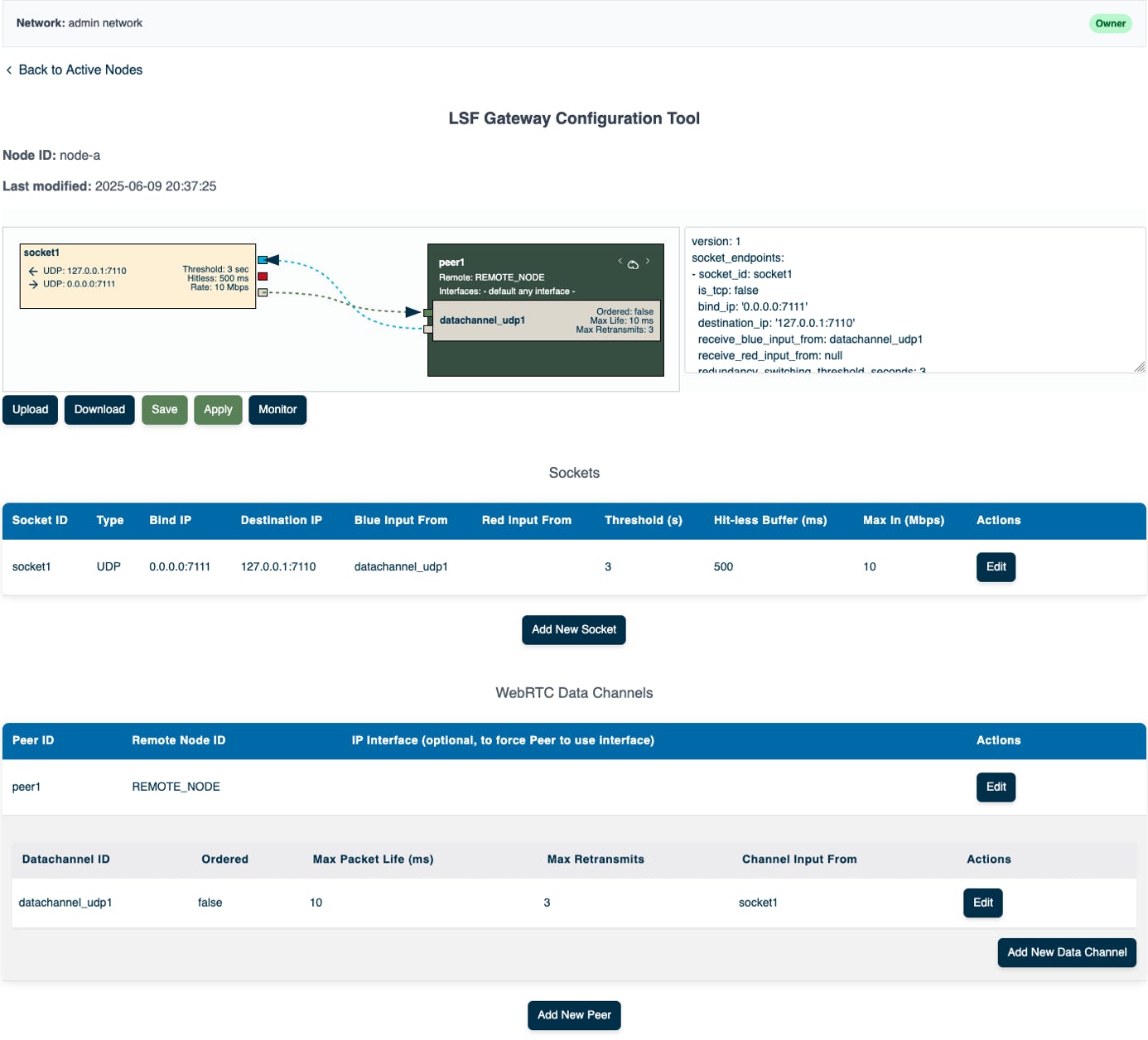
Edit the config for “node-a”
In this example, node-a is configured as the input side of the video stream. It will have a WebRTC data-channel connection to node-b and node-c is the output node.
When configuring the node for the first time, the Configurator adds a simple example configuration which is the one you see when opening the page.
Our video transport configuration is very similar to the default config. Therefore, we just need to make some small modifications to the config above.
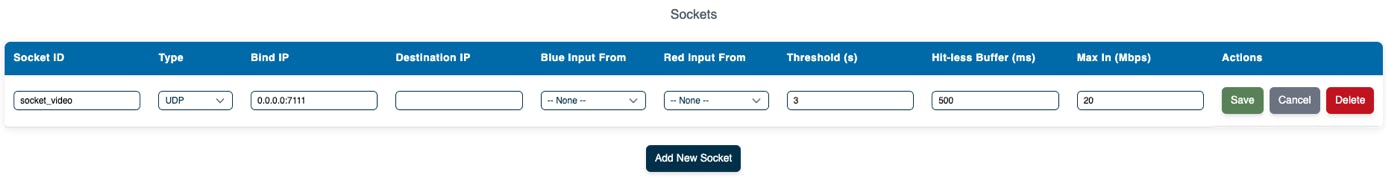
Configure node-a, video input socket:
Click Edit on the socket and configure the values as shown below
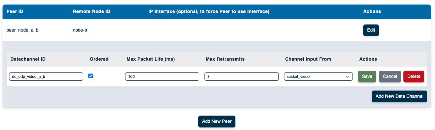
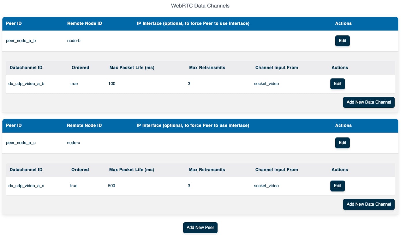
Configure WebRTC Data Channels
In here, we are configuring the WebRTC Peer Connections and the data channels between node-a and node-b and node-c
Navigate to WebRTC Data Channels and click + Edit Peer info
Fill in the fields:
Once the Peer Connection is configured, you can add Data Channels within the WebRTC connection. Typically, you configure one data channel for each IP flow. Fill in the following:
You can experiment with ordered and unordered, max retransmission and max packet life.
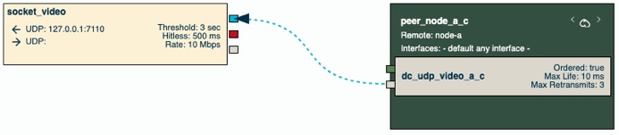
Now, we also need to create a WebRTC Peer config to connect between node-a and node-c. Click on Add New Peer to add a new Peer and data-channel. Use below values.
Click on Add New Data CHannel to add a new data-channel. Use below values.
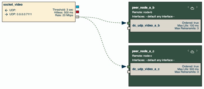
Now we are ready with the configuration of “node-a” which should look like below:
Make sure to save the file on the server by clicking on Save.
Edit the config for “node-b”
node-b is configured as the output side of the video stream. It will have a WebRTC data-channel connection to node-a. It receives the data from node-a and outputs it on a local UDP socket.
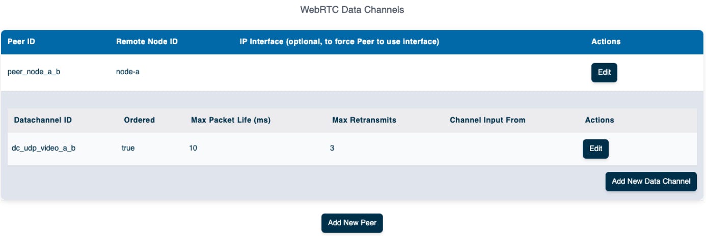
Configure WebRTC Data Channels
In here, we are configuring the WebRTC Peer Connections and the data channels between node-a and node-b
Navigate to WebRTC Data Channels and click + Edit Peer info
Note that the Peer ID and Datachannel ID must be identical with the ones used when you configured node-a.
Fill in the fields:
Once the Peer Connection is configured, you can add Data Channels within the WebRTC connection. Typically, you configure one data channel for each IP flow. Fill in the following:
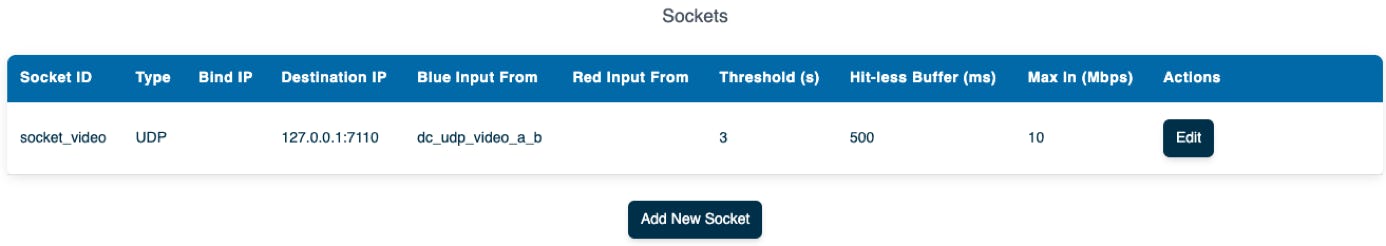
Configure node-b, video output socket
Use the parameters as described below
Socket ID: we need a unique label. We call it “socket_video”
Type: our video feed is a UDP stream
Bind IP: leave empty.
Destination IP: Use whatever IP you are testing with. Could be local interface or another IP address and port number. Could also be a multicast IP address if you with to output the video as a multicast stream.
Blue input From: The input flow to the socket is the webrtc data channel dc_udp_video_a_b.
Red input From: used for output, leave empty.
Threshold: used for output, leave empty.
Hitless buffer: used for output, leave empty.
Max In: used for output, leave empty.
The configuration for node-b should look like below.
Edit the config for “node-c”
node -c is very similar to node-b. Only differences are the WebRTC ID, Datachannel ID and the socket ip address used to output the video stream.
Configure WebRTC Data Channels
Once the Peer Connection is configured, you can add Data Channels within the WebRTC connection. Typically, you configure one data channel for each IP flow. Fill in the following:
Configure node-b, video output socket
The result looks like below:
Start the lsfgateway nodes
At this stage, we are ready with creating the configuration for the nodes. Now it’s time to test the video flow.
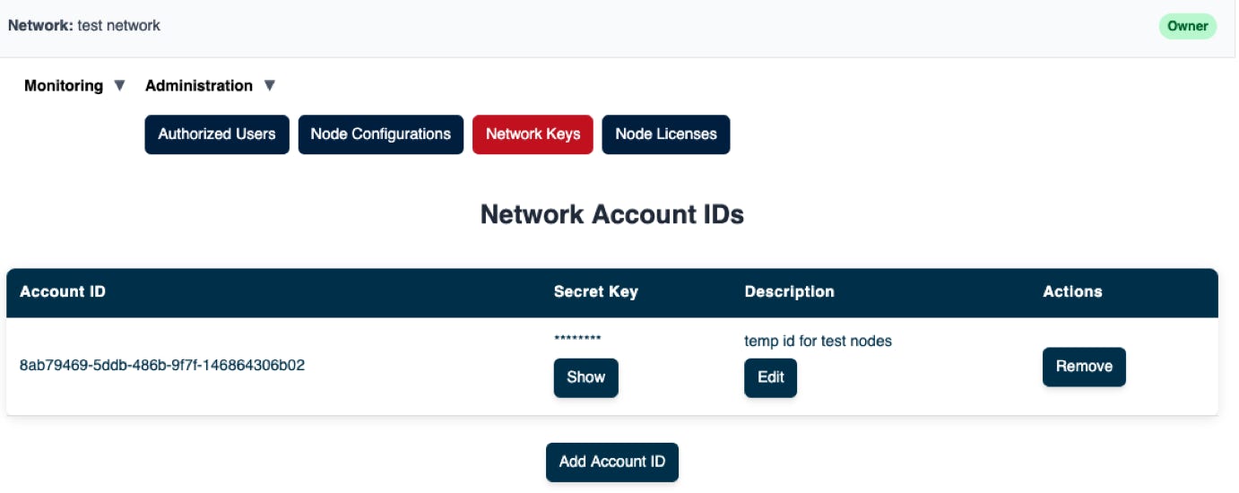
Make sure you have your Account ID and Secret Key that is required to start the lsfgateway nodes. If you don’t have them, you can create new ones.
Start node-a
Start node-b
Start node-c
Check monitoring status of the nodes
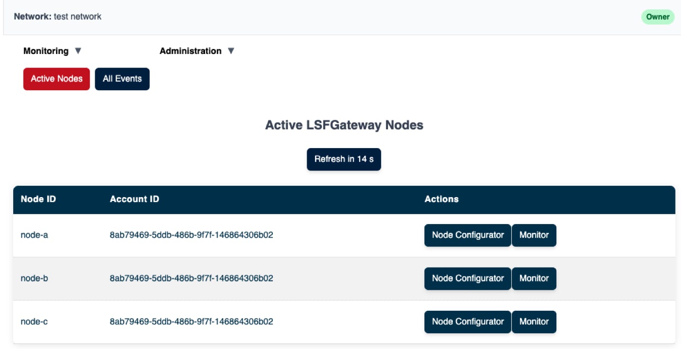
To check status, do the following.
If all nodes are active, you will see them in the LSFManager as shown in the screenshot below:
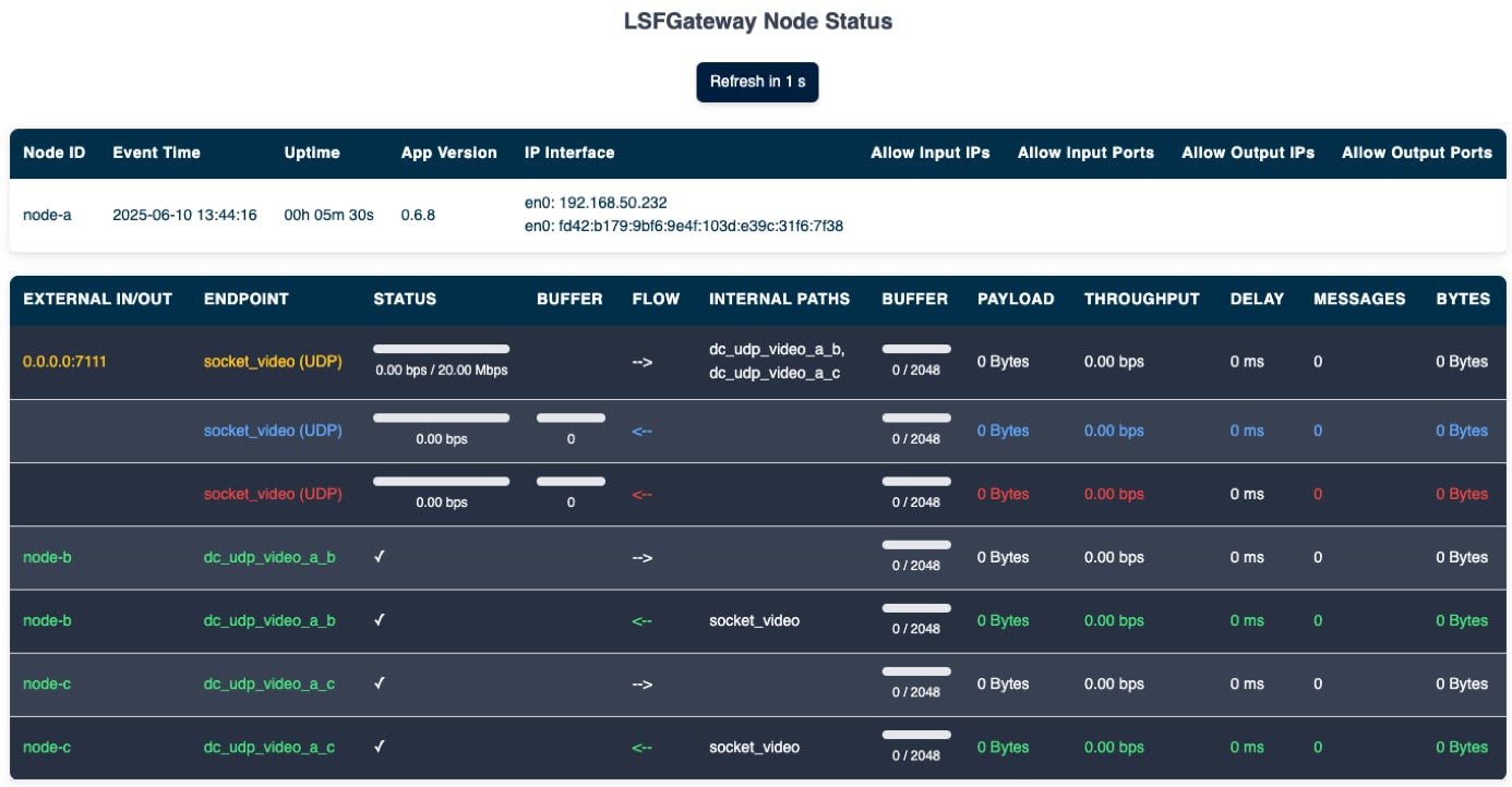
Select Monitor, to see node status. The WebRTC channels (in green), show the status of the peer connections. If the connections are up, you can see a small tick in front of each data-channel id as shown below.
Test video transport
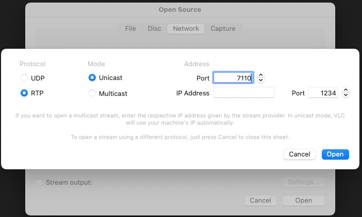
Now it’s ready for the video test. One easy tool to use is VLC media player.
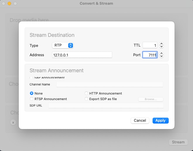
Example of setting up video generator to send to the input on node-a:
And to play the video on node-b and node-c receiving sides, as an example, you could configure the VLC player like below:
./lsfgateway --node_id node-b \
--account_id 8ab79469-5ddb-486b-9f7f-146864306b02 \
--secret_key e657f0e70d78c3bcecdb9670d434982c
./lsfgateway --node_id node-c \
--account_id 8ab79469-5ddb-486b-9f7f-146864306b02 \
--secret_key e657f0e70d78c3bcecdb9670d434982c
© 2025 SOFTSIDE TECH PTY. LTD.