Manual
Welcome to Live Stream Fleet Solution Manual
Manual
Welcome to Live Stream Fleet Solution Manual
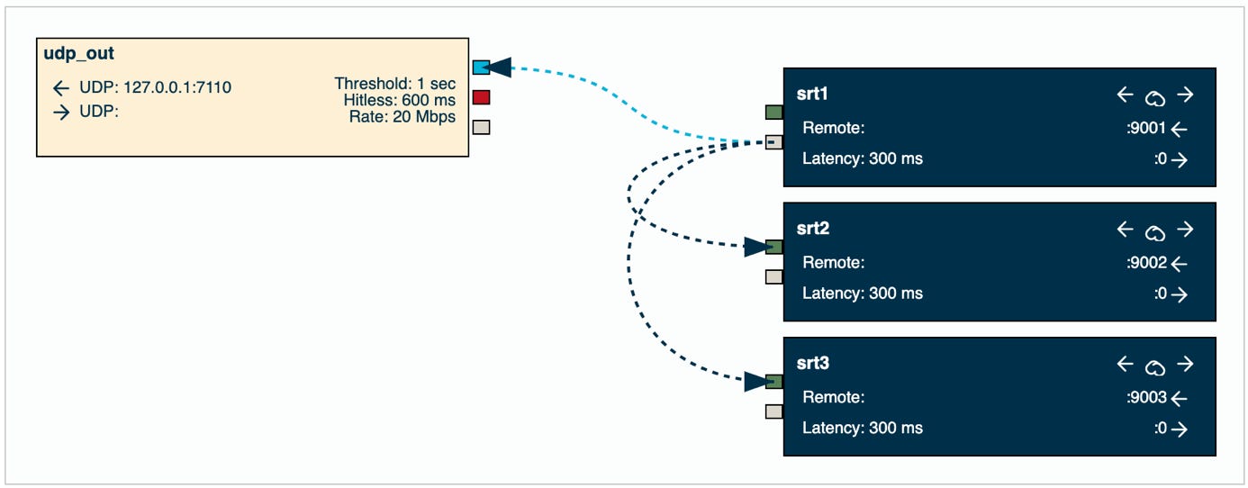
Example: Simple SRT Distribution HUB
./lsfgateway --node_id node-a \
--account_id 8ab79469-5ddb-486b-9f7f-146864306b02 \
--secret_key e657f0e70d78c3bcecdb9670d434982c
This is a straightforward standalone illustration demonstrating the process of receiving a single SRT feed, transmitting it via a local UDP socket, and simultaneously replicating the same data flow to two distinct SRT connections.
Below is a diagram illustrating the configuration we will implement.
Prerequisites:
First, please make sure you have installed one lsfgateway node and that you have access to the LSF Manager web app, following the instructions in the Config Prerequisites page.
Edit the config for “node-a”
If you do not have a configuration for node_a already, please create one as described below.
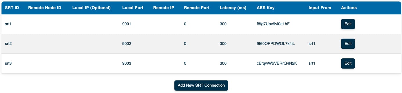
Configure three SRT Listeners:
For instance, we can configure three SRT listeners, named “srt1”, “srt2” and “srt3”. In our scenario, “srt1” will receive a video feed and forward it to “srt2”, “srt3”, and a local UDP socket.
Below are the configuration parameters for this example:
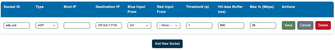
Configure node-a, video input socket:
Click Add New Socket, and add the values below:
Make sure to save the file on the server by clicking on Save.
Start the lsfgateway nodes
At this stage, we are ready with creating the configuration for the nodes. Now it’s time to test the video flow.
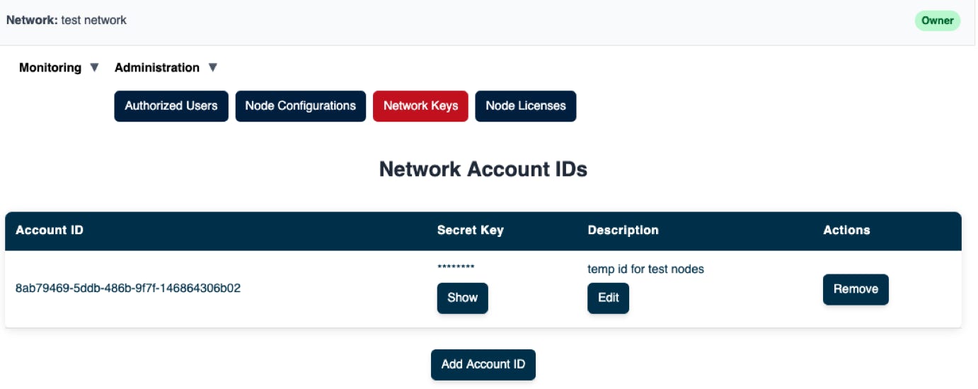
Make sure you have your Account ID and Secret Key that is required to start the lsfgateway nodes. If you don’t have them, you can create new ones.
Start node-a
Check monitoring status of the nodes
To check status, do the following.
© 2025 SOFTSIDE TECH PTY. LTD.